困惑了将近一年多的ModbusRTU在我昨天穷极无聊给自己定目标的情况下搞出来了,以前移植不出来主要原因就是基本功不扎实,没有进一步理解串口和定时器配置的原理,一通操作,移植完之后就Timeout,接下来就一下我是怎么从0开始移植这个协议的。 项目已上传码云,文章底部有链接! 操作之前先讲两个主要问题 MoubusRTU移植到stm32平台通信是通过串口进行通信,主要是需要串口进行收发,所以发送中断时必须的,在波特率设置问题上是和定时器相关联,在mbrtu.c文件的eMBRTUInit函数里具体说明了串口波特率和定时器设置的关系 从上面代码的注释中可以看出,当波特率大于19200时,超时时间固定位为1750us,当波特率小于19200时,超时时间为3.5个字符时间,具体计算公式在代码注释里已经有了,这里我就不多赘述。本人波特率使用115200,所以按照1750us来。 ModbusRTU是通过定时器和串口配合来实现Modbus通信的,所以定时器是决定有没有超时的一大关键问题,由串口设置部分可知,定时器设置是要配合串口设置的波特率食用比较香,所以根据我使用的115200波特率可以得到我定时器设置。首先是APB1的主频率获取到,modbus要求通过预分配后得到的周期为50us,对应频率为20KHz。根据rtu初始化代码得到自动重载值设置为35。 我直接贴代码,自己对比我的代码和源码差距,关键地方我会在后边标注 我直接贴代码,自己对比我的代码和源码差距,关键地方我会在后边标注 位置在port.h文件的32行和33行,修改为如下所示,并在port.h前包含上stm32的hal库,如图所示 打开工程内的中断文件,是在Application/User–>stm32f7xx_it.c 找到自己设置的串口中断处理函数,添加如下代码,用于将串口收到的内容移动到modbus功能函数进行处理 在Application/User–>stm32f7xx_it.c末尾的/* USER CODE BEGIN 1 */添加定时器中断回调函数如下: 到此,串口和定时器的问题已经处理完毕,接下来是modbus的配置 硬件接口方面结束之后就可以开始写功能了,在MB–>demo.c中有功能示例,我们根据功能示例来修改对应的功能并使能modbus,这里我只说输入寄存器功能,其它的一次类推,就不多赘述。 启动modbus需要在main函数进行初始化、开启侦听操作,需要添加以下代码,对应位置可在mian函数找到 至此修改完毕,编译下载之后即可使用modbus poll进行连接测试。 将上述代码编译下载到板子,用TTL转USB接入PC,找到在PC的对应端口即可打开ModbusPoll进行通信测试 至此,freeModbusRTU移植成功!,具体代码已上传,详见我的码云F7_ModbusRTU 做完事情就要去打一下游戏!
1.需要的材料
2.操作步骤
1.串口设置问题
eMBErrorCode eMBRTUInit( UCHAR ucSlaveAddress, UCHAR ucPort, ULONG ulBaudRate, eMBParity eParity ) { eMBErrorCode eStatus = MB_ENOERR; ULONG usTimerT35_50us; ( void )ucSlaveAddress; ENTER_CRITICAL_SECTION( ); /* Modbus RTU uses 8 Databits. */ if( xMBPortSerialInit( ucPort, ulBaudRate, 8, eParity ) != TRUE ) { eStatus = MB_EPORTERR; } else { /* If baudrate > 19200 then we should use the fixed timer values * t35 = 1750us. Otherwise t35 must be 3.5 times the character time. */ if( ulBaudRate > 19200 ) { usTimerT35_50us = 35; /* 1750us. */ } else { /* The timer reload value for a character is given by: * * ChTimeValue = Ticks_per_1s / ( Baudrate / 11 ) * = 11 * Ticks_per_1s / Baudrate * = 220000 / Baudrate * The reload for t3.5 is 1.5 times this value and similary * for t3.5. */ usTimerT35_50us = ( 7UL * 220000UL ) / ( 2UL * ulBaudRate ); } if( xMBPortTimersInit( ( USHORT ) usTimerT35_50us ) != TRUE ) { eStatus = MB_EPORTERR; } } EXIT_CRITICAL_SECTION( ); return eStatus; } 2.定时器设置问题
具体操作:
熟悉stm32cubemx的老司机可以直接从15步看起
1.选择MCU型号

2.使能时钟源RCC为外部时钟

3.配置时钟树,记录APB1频率,我这里是36MHz

4.使能定时器4,预分频系数为1800-1,对应的分频频率为20KHz,不懂的回到上面去看定时器设置解析,自动重载值设置为35,得到超时时间1750us。

5.使能定时器中断

6.配置串口2,选择异步通信后参数设置为115200,8,NONE,1

7.使能串口中断

8.配置中断优先级,定时器中断优先级低于串口中断即可

9.配置项目参数并分离头文件和c文件后生成代码。


10.打开freeModbus代码包的demo文件夹,新建一个名为STM32MB的文件夹,之后将BARE文件夹内所有内容复制到STM32MB文件夹下,复制完成如图

11.回到freeModbus代码包,复制整个modbus文件夹也粘贴到STM32MB文件夹内,完成效果如图

12.将STM32MB文件夹移动到stm32cubeMX生成的工程目录下,如图

13.打开工程,引入STM32MB内的所有头文件,并新建名为MB和MB_Port的组,MB内添加STM32MB文件夹下modbus文件夹内所有c文件以及根目录的demo.c文件,MB_Port内添加STM32MB文件夹下port文件夹内所有c文件,如图所示


14.修改demo.c文件夹的main函数名为host,编译不报错即可开始修改,如图所示

以下为正式修改Modbus代码,上面比较繁琐,熟悉stm32cubemx的老司机可以直接从15步看起15.修改MB_Port下的portserial.c文件(串口设置)
#include "port.h" #include "stm32f7xx_hal.h" #include "usart.h" /* ----------------------- Modbus includes ----------------------------------*/ #include "mb.h" #include "mbport.h" /* ----------------------- static functions ---------------------------------*/ //static void prvvUARTTxReadyISR( void ); //static void prvvUARTRxISR( void ); /* ----------------------- Start implementation -----------------------------*/ void vMBPortSerialEnable( BOOL xRxEnable, BOOL xTxEnable ) { /* If xRXEnable enable serial receive interrupts. If xTxENable enable * transmitter empty interrupts. */ if (xRxEnable) //将串口收发中断和modbus联系起来,下面的串口改为自己使能的串口 { __HAL_UART_ENABLE_IT(&huart2,UART_IT_RXNE); //我用的是串口2,故为&huart2 } else { __HAL_UART_DISABLE_IT(&huart2,UART_IT_RXNE); } if (xTxEnable) { __HAL_UART_ENABLE_IT(&huart2,UART_IT_TXE); } else { __HAL_UART_DISABLE_IT(&huart2,UART_IT_TXE); } } BOOL xMBPortSerialInit( UCHAR ucPORT, ULONG ulBaudRate, UCHAR ucDataBits, eMBParity eParity ) { return TRUE; //改为TURE,串口初始化在usart.c定义,mian函数已完成 } BOOL xMBPortSerialPutByte( CHAR ucByte ) { /* Put a byte in the UARTs transmit buffer. This function is called * by the protocol stack if pxMBFrameCBTransmitterEmpty( ) has been * called. */ if(HAL_UART_Transmit (&huart2 ,(uint8_t *)&ucByte,1,0x01) != HAL_OK ) //添加发送一位代码 return FALSE ; else return TRUE; } BOOL xMBPortSerialGetByte( CHAR * pucByte ) { /* Return the byte in the UARTs receive buffer. This function is called * by the protocol stack after pxMBFrameCBByteReceived( ) has been called. */ if(HAL_UART_Receive (&huart2 ,(uint8_t *)pucByte,1,0x01) != HAL_OK )//添加接收一位代码 return FALSE ; else return TRUE; } /* Create an interrupt handler for the transmit buffer empty interrupt * (or an equivalent) for your target processor. This function should then * call pxMBFrameCBTransmitterEmpty( ) which tells the protocol stack that * a new character can be sent. The protocol stack will then call * xMBPortSerialPutByte( ) to send the character. */ //static void prvvUARTTxReadyISR( void ) //删去前面的static,方便在串口中断使用 { pxMBFrameCBTransmitterEmpty( ); } /* Create an interrupt handler for the receive interrupt for your target * processor. This function should then call pxMBFrameCBByteReceived( ). The * protocol stack will then call xMBPortSerialGetByte( ) to retrieve the * character. */ //static void prvvUARTRxISR( void ) //删去前面的static,方便在串口中断使用 { pxMBFrameCBByteReceived( ); } 16.修改MB_Port下的porttimer.c文件(定时器设置)
#include "port.h" #include "stm32f7xx_hal.h" #include "tim.h" /* ----------------------- Modbus includes ----------------------------------*/ #include "mb.h" #include "mbport.h" /* ----------------------- static functions ---------------------------------*/ //static void prvvTIMERExpiredISR( void ); /* ----------------------- Start implementation -----------------------------*/ BOOL xMBPortTimersInit( USHORT usTim1Timerout50us ) //定时器初始化直接返回TRUE,已经在mian函数初始化过 { return TRUE; } inline void vMBPortTimersEnable( ) //使能定时器中断,我用的是定时器4,所以为&htim4 { /* Enable the timer with the timeout passed to xMBPortTimersInit( ) */ __HAL_TIM_CLEAR_IT(&htim4,TIM_IT_UPDATE); __HAL_TIM_ENABLE_IT(&htim4,TIM_IT_UPDATE); __HAL_TIM_SetCounter(&htim4,0); __HAL_TIM_ENABLE(&htim4); } inline void vMBPortTimersDisable( ) //取消定时器中断 { /* Disable any pending timers. */ __HAL_TIM_DISABLE(&htim4); __HAL_TIM_SetCounter(&htim4,0); __HAL_TIM_DISABLE_IT(&htim4,TIM_IT_UPDATE); __HAL_TIM_CLEAR_IT(&htim4,TIM_IT_UPDATE); } /* Create an ISR which is called whenever the timer has expired. This function * must then call pxMBPortCBTimerExpired( ) to notify the protocol stack that * the timer has expired. */ //static void prvvTIMERExpiredISR( void ) //modbus定时器动作,需要在中断内使用 { ( void )pxMBPortCBTimerExpired( ); } 17.修改完Modbus与stm32的接口文件之后要在port.h文件内定义总中断
#define ENTER_CRITICAL_SECTION( ) __set_PRIMASK(1) //关总中断 #define EXIT_CRITICAL_SECTION( ) __set_PRIMASK(0) //开总中断 #include "stm32f7xx_hal.h" 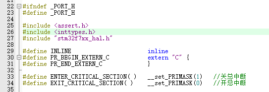
modbus端口函数到此修改完成,接下来是中断函数18.串口及定时器中断修改
根据板子不同而不同,区别是stm32f后面的数字。知道是中断管理文件就行
在/* USER CODE BEGIN PFP */后添加以下代码,用于和modbus的串口和定时器功能代码联系extern void prvvUARTTxReadyISR(void); extern void prvvUARTRxISR(void); extern void prvvTIMERExpiredISR( void ); void USART2_IRQHandler(void) { /* USER CODE BEGIN USART2_IRQn 0 */ /* USER CODE END USART2_IRQn 0 */ HAL_UART_IRQHandler(&huart2); /* USER CODE BEGIN USART2_IRQn 1 */ if(__HAL_UART_GET_IT_SOURCE(&huart2, UART_IT_RXNE)!= RESET) { prvvUARTRxISR();//接收中断 } if(__HAL_UART_GET_IT_SOURCE(&huart2, UART_IT_TXE)!= RESET) { prvvUARTTxReadyISR();//发送中断 } HAL_NVIC_ClearPendingIRQ(USART2_IRQn); HAL_UART_IRQHandler(&huart2); /* USER CODE END USART2_IRQn 1 */ } void HAL_TIM_PeriodElapsedCallback(TIM_HandleTypeDef *htim) //定时器中断回调函数,用于连接porttimer.c文件的函数 { /* NOTE : This function Should not be modified, when the callback is needed, the __HAL_TIM_PeriodElapsedCallback could be implemented in the user file */ prvvTIMERExpiredISR( ); } 19.modbus功能处理
这里也是直接贴代码,大概说一下,就是自己设置一个数组,将数据放到数组内,并在被读取时根据数据位置将数据返回去/* ----------------------- Modbus includes ----------------------------------*/ #include "mb.h" #include "mbport.h" /* ----------------------- Defines ------------------------------------------*/ #define REG_INPUT_START 0 #define REG_INPUT_NREGS 5 /* ----------------------- Static variables ---------------------------------*/ static USHORT usRegInputStart = REG_INPUT_START; //static uint16_t usRegInputBuf[REG_INPUT_NREGS]; uint16_t InputBuff[5]; eMBErrorCode eMBRegInputCB( UCHAR * pucRegBuffer, USHORT usAddress, USHORT usNRegs ) { eMBErrorCode eStatus = MB_ENOERR; int iRegIndex; int i; InputBuff[0] = 0x11; InputBuff[1] = 0x22; InputBuff[2] = 0x33; InputBuff[3] = 0x44; if( ( usAddress >= REG_INPUT_START ) && ( usAddress + usNRegs <= REG_INPUT_START + REG_INPUT_NREGS ) ) { iRegIndex = ( int )( usAddress - usRegInputStart ); for(i=0;i<usNRegs;i++) { *pucRegBuffer=InputBuff[i+usAddress-1]>>8; pucRegBuffer++; *pucRegBuffer=InputBuff[i+usAddress-1]&0xff; pucRegBuffer++; } } else { eStatus = MB_ENOREG; } return eStatus; } eMBErrorCode eMBRegHoldingCB( UCHAR * pucRegBuffer, USHORT usAddress, USHORT usNRegs, eMBRegisterMode eMode ) { return MB_ENOREG; } eMBErrorCode eMBRegCoilsCB( UCHAR * pucRegBuffer, USHORT usAddress, USHORT usNCoils, eMBRegisterMode eMode ) { return MB_ENOREG; } eMBErrorCode eMBRegDiscreteCB( UCHAR * pucRegBuffer, USHORT usAddress, USHORT usNDiscrete ) { return MB_ENOREG; } 20.modbus启动
/* USER CODE BEGIN Includes */ #include "mb.h" #include "mbport.h" /* USER CODE END Includes */ /* USER CODE BEGIN 2 */ eMBInit( MB_RTU, 0x01, 1, 115200, MB_PAR_NONE);//初始化modbus,走modbusRTU,从站地址为0x01,端口为1。 eMBEnable( );//使能modbus /* USER CODE END 2 */ /* USER CODE BEGIN WHILE */ while (1) { /* USER CODE END WHILE */ /* USER CODE BEGIN 3 */ ( void )eMBPoll( );//启动modbus侦听 } /* USER CODE END 3 */ 21.modbus测试
代码下载成功后打开ModbusPoll,打开读写定义并设置为从站地址1,功能04读输入寄存器,起始地址0,长度为4,如图所示


按F3进行连接,连接设置如图,串口所在位置会显示TTL转串口的芯片型号,按照如下设定后确定。

即可得到下图,由于我们输入寄存器存放的是16进制数,所以要将ModbusPoll显示模式改为16进制才能显示相同内容


最终效果如下图,ModbusPoll读取的值与STM32内寄存器内的值一致,读取成功!

希望大家不要白piao,评论打赏素质三连!!!
本网页所有视频内容由 imoviebox边看边下-网页视频下载, iurlBox网页地址收藏管理器 下载并得到。
ImovieBox网页视频下载器 下载地址: ImovieBox网页视频下载器-最新版本下载
本文章由: imapbox邮箱云存储,邮箱网盘,ImageBox 图片批量下载器,网页图片批量下载专家,网页图片批量下载器,获取到文章图片,imoviebox网页视频批量下载器,下载视频内容,为您提供.
阅读和此文章类似的: 全球云计算
 官方软件产品操作指南 (170)